Motorized Stages
Guide
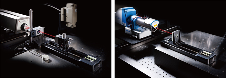
Accuracy Verification
Motorized stage accuracy is, in principle, confirmed in compliance with the JIS test code
for machine tools (JIS B 6190).
In addition, all measuring instruments are traceable standard instruments
compliant to the national standard.
| Category | Measurement Item | Device Used | Standards |
|---|---|---|---|
| Linear Stage | Positioning Accuracy | Dynamic Calibrator (HP5529A) |
JIS B 6190 |
| Positional Repeatability | |||
| Lost Motion | |||
| Running Parallelism | Dial Indicator | Company Standard | |
| Pitch/Yaw | Auto Collimator | Company Standard |
It has to be guaranteed that measured values and indicated values are within the specification range of international standard values. In other words, traceability must be ensured. JIS defined this traceability as “the capacity to trace measurement results back to the domestic measurement standards, with the use of measuring instruments that have gone through a sequence of calibrations with high-ranking standards.”
| Category | Measurement Item | Device Used | Standards |
|---|---|---|---|
| Rotation Stage | Positional Repeatability | Rotary Encoder | Company Standard |
| Lost Motion | |||
| Wobble Accuracy | Dial Indicator | Company Standard | |
| Goniometer Stage | Positional Repeatability | Rotary Encoder | Company Standard |
| Lost Motion | |||
| Rotation Center Height | Three Dimensional Instrumentation | Company Standard | |
| Rotation Center Deviation Accuracy |
Accuracy Check in Assembled State
We check accuracy of motorized stages as a single unit.
Regarding the accuracy check in assembled state,
we need to confirm use conditions etc. Contact our International Sales Division separately.
Accuracy Check at Delivery Destination
We cannot conduct accuracy check at delivery destinations.
We will request a check from organizations such
as Japan Quality Assurance Organization as necessary.
Contact our International Sales Division separately
for more information.
Interpretation of the Specification Table
- Part Number
- Opposite Model
Mechanical Specifications
- Travel
Indicates the full travel.
- Table Size
Size of top table face.
- Feed Screw
* Ball screw
* Precision ground screws - Positioning Slide
* Outer rail structure
* Crossed roller guide - Stage Material
Material used for the product.
- Weight
Self weight of the product.
Accuracy SpecificationsRefer to the accuracy verification page for more information.
-
Resolution (Half)
Travel per pulse for full step
Resolution (Full)Travel per pulse for half step
- MAX Speed
MAX speed of the product (maximum travel speed).
- Positioning Accuracy
Deviation between the measured value and the target value at the positioning point.
- Positional Repeatability
Deviation in stop positions when unidirectional positioning is performed multiple times.
- Load Capacity
Load capacity at the center of the stage
-
Moment Stiffness
Stage strength against a load exerted at a position away from the center of the table top (the table center and the center of gravity of a work does not match).
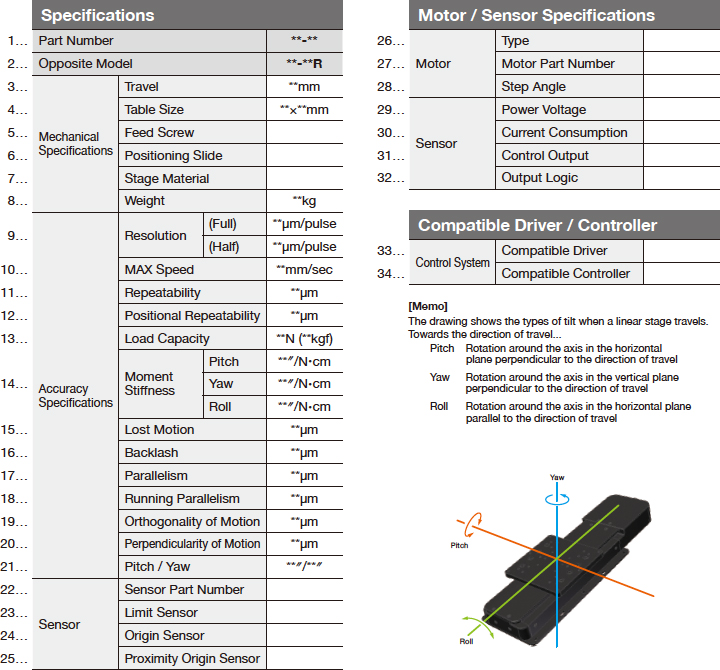
It indicates the degree of tilt of the table top (″) when 1N load is exerted at the position 1cm away from the center of the stage surfacePitchStiffness in the direction of tilt around the axis in the horizontal plane perpendicular to the direction of travel when moving the stage for full travel.
YawStiffness in the direction of tilt around the axis in the vertical plane perpendicular to the direction of travel when moving the stage for full travel.
RollStiffness in the direction of tilt around the axis in the horizontal plane parallel to the direction of travel when moving the stage for full travel.
- Lost Motion
Deviation between the stop position of forward positioning and that of backward positioning.
- Backlash
Deviation in each direction when a certain load is exerted in forward and backward directions at an arbitrary position on the stage.
- Parallelism
The parallelism of the table fixed on the stage against the base plane.
* Note that it is different from “Running Parallelism”. - Running Parallelism
Displacement in the vertical direction of the table during stage motion along the full travel.
- Orthogonality of Motion
Working displacement in the direction perpendicular to the Y axis when referenced to the X axis motion of the XY axis stage.
- Perpendicularity of Motion
Displacement between the Z axis stage and the perpendicular optical breadboard when moving the stage for full travel.
-
Pitch
Maximum angle displacement in the direction of tilt around the axis in the horizontal plane perpendicular to the direction of travel when moving the stage for full travel.
YawMaximum angle displacement in the direction of tilt around the axis in the vertical plane perpendicular to the direction of travel when moving the stage for full travel.
Sensor - Sensor Part Number
Sensor used for the product.
- Limit Sensor
Indicates whether fitted with a limit sensor.
- Origin Sensor
Indicates whether fitted with an origin sensor.
- Proximity Origin Sensor
Indicates whether fitted with a proximity origin sensor.
Motor Specifications - Type
Type of motor.
- Motor Part Number
Part number of motor used for the product.
- Step Angle
Step angle of the motor.
Sensor Specifications - Power Voltage
- Current Consumption
Specifications of the sensor.
- Control Output
- Output Logic
Compatible Driver / Controller
- Compatible Driver
Driver/controller compatible with the product.
- Compatible Controller