Custom 12 Axis Fiber Aligment System
1. System Overview
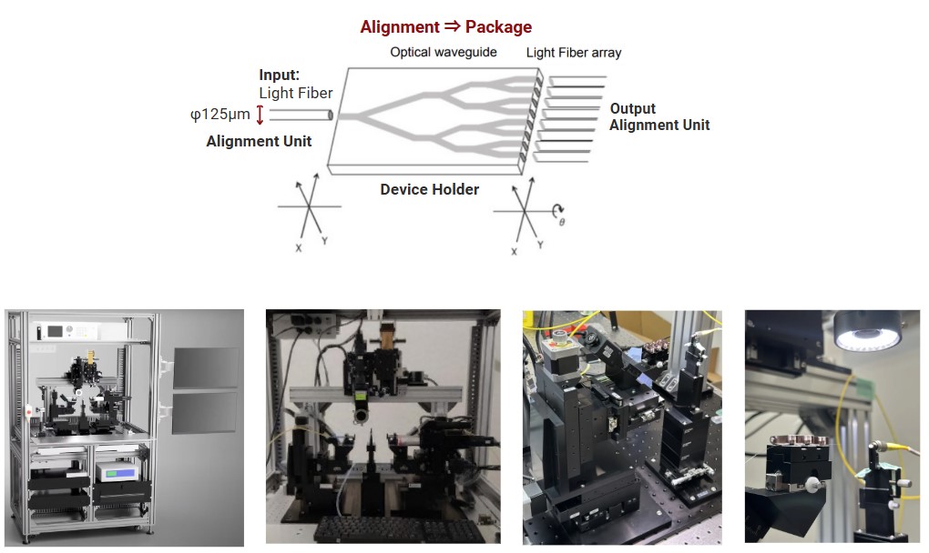
The automatic 12-axis fiber alignment system is designed for precise alignment of optical fibers, optical waveguides, and fiber arrays to ensure efficient optical signal transmission. Configurable for labs or production — balancing speed, accuracy, and repeatability in setups ranging from standard tasks to complex optical integrations.


* Units and Components Available
* Tailored to unique application requirements
Key Features:
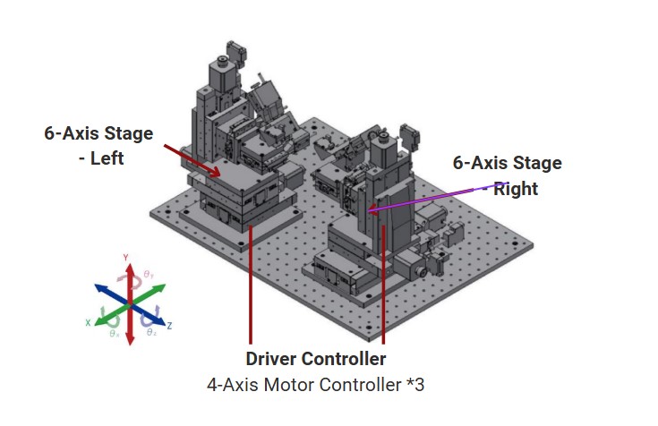
(1)12-Axis Motion Control
Two 6-axis alignment stages (left and right) with combined
linear and rotational motion.
(1)Real-Time Observation & Imaging
Includes a CMOS camera and ring light for live
monitoring.
(1)Precision Alignment Algorithms
Supports raster, spiral, Nelder-Mead, and line
optimization for accurate alignment.
(1)User-Friendly Software
SGAlign software provides real-time control, data storage, and
customizable alignment sequences.
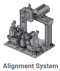
2. Components of Alignment System
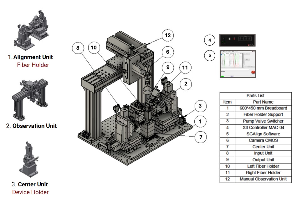
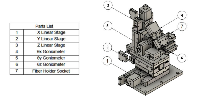
2. 1 Alignment Unit
This unit consists of two 6-axis alignment stages for precise movement and positioning of optical fibers and waveguides.
- High-resolution stages ensure precise, rigid, and efficient alignment.
- Magnetic mounts and positioning mechanisms guarantee consistent, repeatable placement.
- Compatible with multiple holders (fiber, rotation, array, etc.) for versatile setups.
System Components
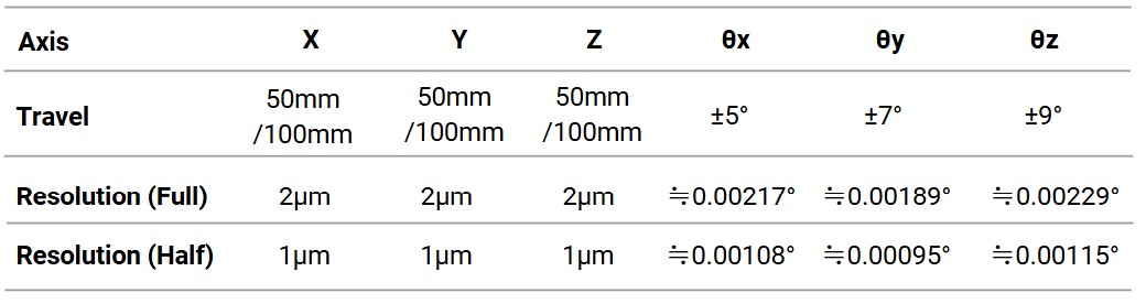
Positioning Specifications
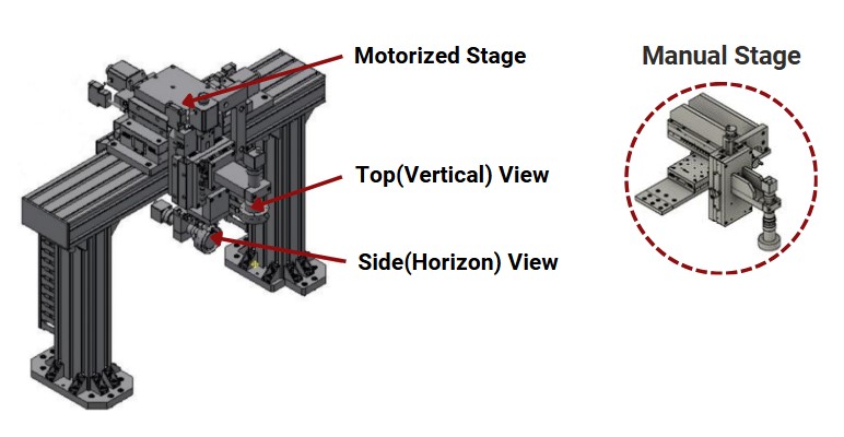
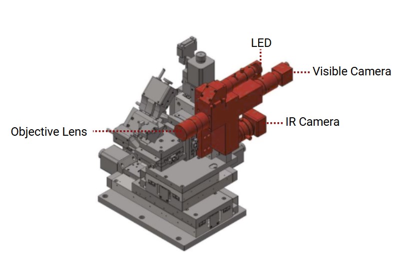
2.2 Observation Unit
This unit enables real-time visualization of the alignment process — waveguide end faces, fiber end faces, devices, etc.
- XYZ Linear Stages for precise movement.
- CMOS Camera for real-time imaging.
- Ring Light for enhanced visibility.
- Vertical Observation: Standard with variable magnification.
- Horizontal Observation: Fixed magnification (1x), optional zoom lens.
Common Specfications
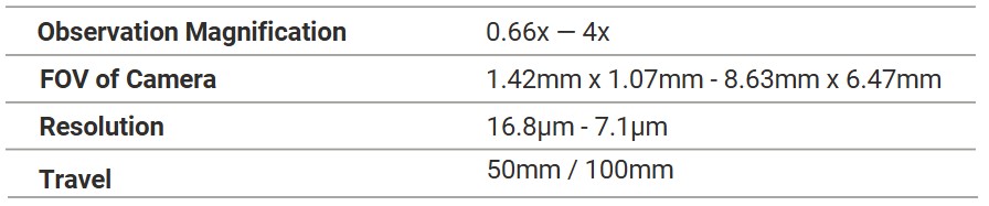
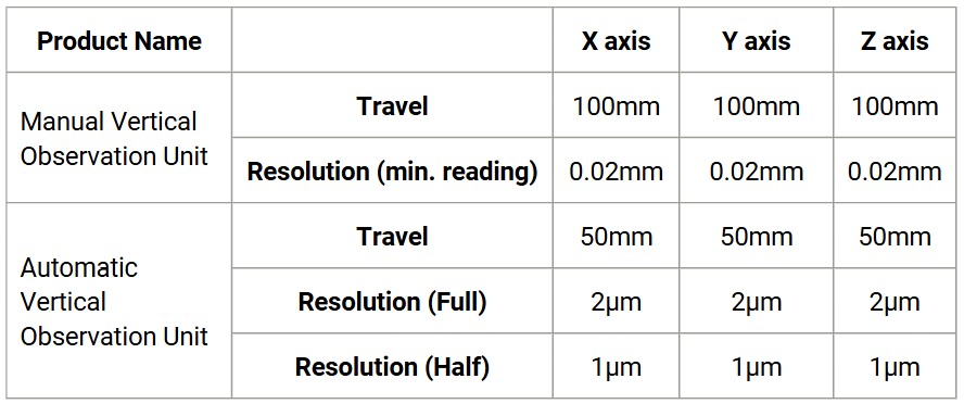
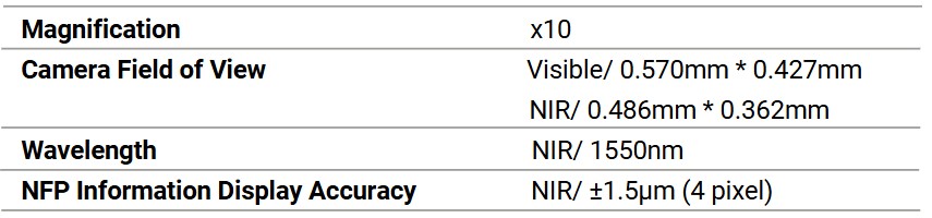
Vertical Observation Specifications
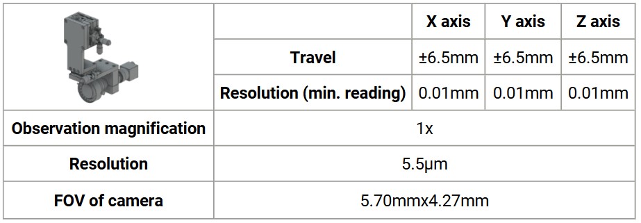
Horizontal Observation Specifications
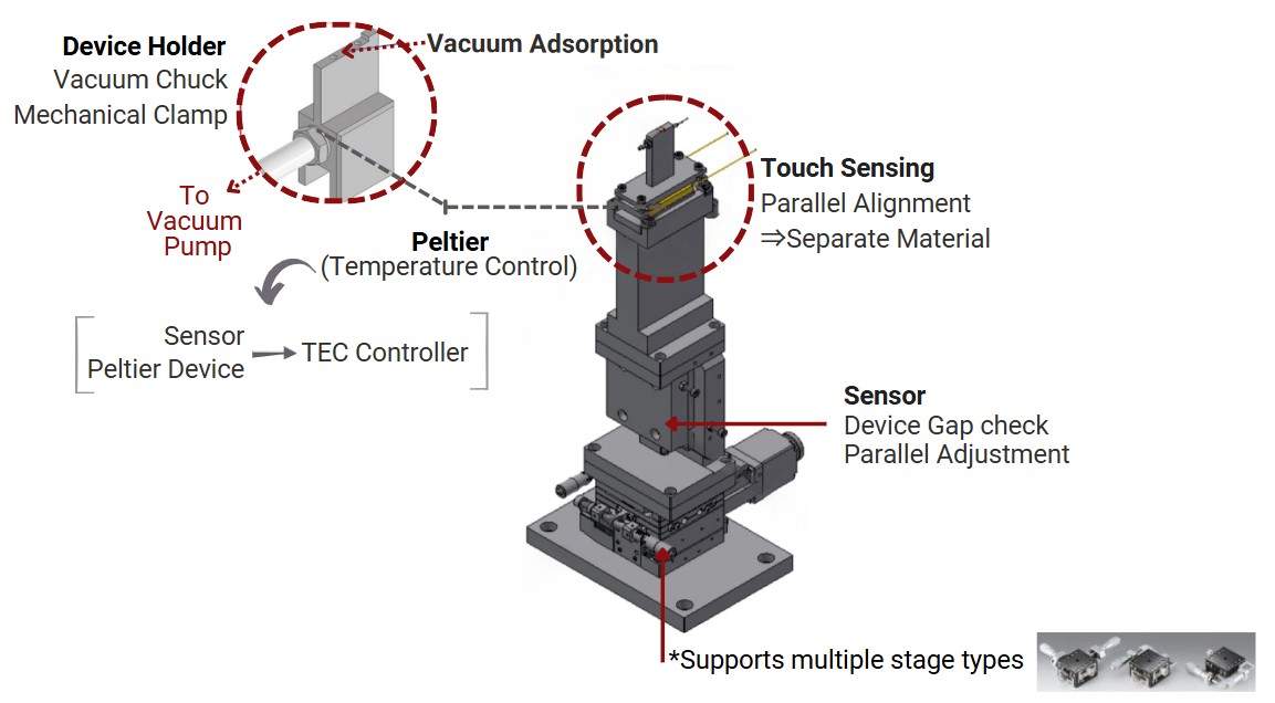
2.3 Center Unit
This unit is designed for precise alignment of 3–8 mm waveguides, serving as the core control hub for the alignment process.
- Sample Fixation: Secure samples via absorption or mechanical clamping.
- Compatible Sizes: Supports 5mm × 5mm and 10mm × 10mm samples.
- Adjustment: Manual 2-axis stage for fine-tuning position and angle.
- Customization: Optional temperature control or contact sensors to meet specific requirements.
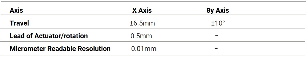
CEUT Common Specifications (Manual Stage Part)
3. NFP Observation Unit / NFP-KIT (Option)
- A versatile observation system with control software for easy and precise measurement of beam diameter (NFP).
- When combined with an automatic alignment unit, it allows for quick adjustments based on luminance values, making it ideal for evaluating optical fibers and waveguides.
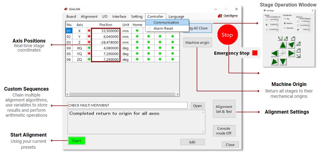
4. Software: SGAlign
The SGAlign software provides an intuitive interface for alignment, offering:
- Real-Time Position Monitoring
- Customizable Alignment Sequences
- Power Measurement and Optimization
- Automated Multi-Step Alignment
5. Applications
- TOSA/ROSA Assembly
- Waveguide Alignment and Testing
- Lens Array and Fiber Array Alignment
- Fiber Alignment and Testing
- Optical Switch Assembly
- CWDM Module Assembly
- Pitch Conversion for Ribbon Fiber
Elevate your optical precision with our customizable alignment solutions.
For tailored support and expert guidance, please email us at: